PDF Design and Simulation of a Smart Traffic System in a Campus Circuit Diagram
PDF Design and Simulation of a Smart Traffic System in a Campus Circuit Diagram Determines the state of the traffic signal based on the received signal. Traffic Signal Control: Dynamically adjusts traffic signals based on the received signal: Signals 1 and 4 activate the first set of signals. Signals 2 and 3 activate the second set of signals. Signal 5 turns off all signals, indicating no vehicles. Signal Timing Simulation: This is a smart 4-way traffic light system. The pedestrian lights work such that whenever a certain traffic light is green its opposite pedestrian lights turn on. An addition of ultrasonic sensors have been made in the traffic light sequence.

Must-have features for a smart traffic light system. Smart traffic light technology adds a new dimension of real-time control — and many good things come as a result: Reduced travel times. The average American spends 58 hours per year waiting at traffic lights. Smarter controls can make people and goods move faster through city arteries. In order to make a Smart Traffic Management system with Arduino, we will require the following components. Components. Arduino Uno R3; By using real-time traffic data, you can optimize signal timing to reduce congestion and improve safety for drivers, cyclists, and pedestrians and, ultimately, make your community a better place to live.
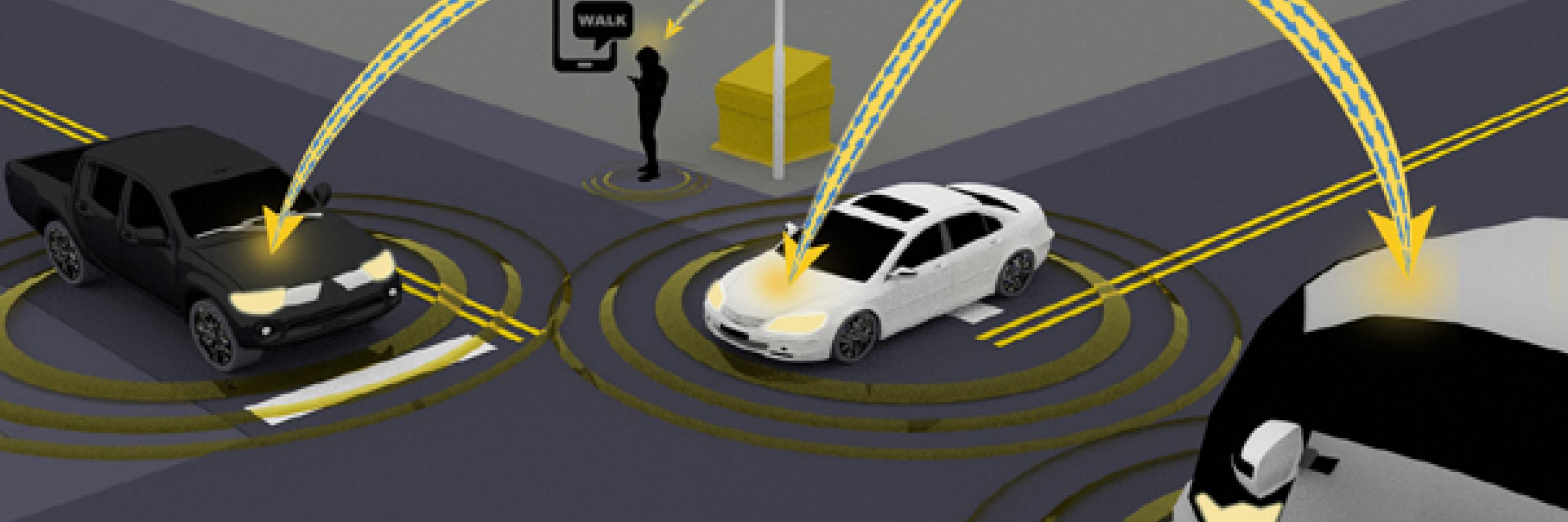
How do smart traffic lights work? Technology overview Circuit Diagram
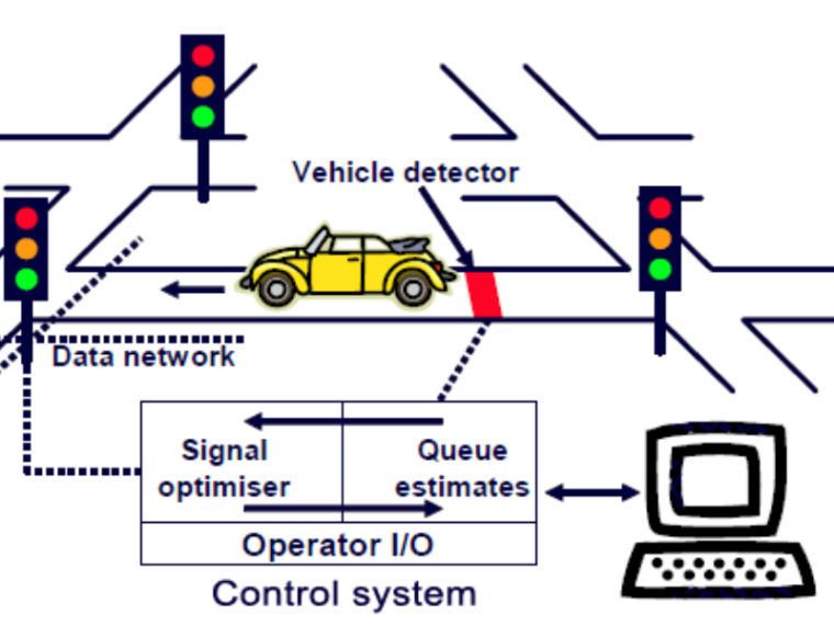
Creating a smart traffic management system can significantly improve urban mobility. This system can monitor traffic flow, manage signals, and provide real-time updates to drivers. This is where the data is analyzed to make decisions. Traffic Signal Control: This component adjusts the timing of traffic lights based on real-time data.
In this project, we are going to make a traffic light control for a four-way intersection. We will learn about traffic lights and how they work through an electronic project. This project is a condensed version of the four-side or direction traffic light system that we have exhibited. Required components: Arduino; 12 pieces of 220-ohm resistors Welcome to the ESP32 Learning Series! In this tutorial, we'll show you how to build a smart traffic signal system using the ESP32. Learn how to control traff Two-way traffic signal using ultrasonic sensor and Arduino which take decisions on the basis of density. In this video, we are going to make a traffic signal and they will be controlled autonomously by checking the density using the ultrasonic sensor. A prototype to smart transport. I have used proteus simulation but you can use the same code for real components.
Build a Smart Traffic Light ... Circuit Diagram
Circuit Diagram. Hookup Hook the GND pin (Negative Pin) of all led to Pin GND of Arduino. Connect Red LED VCC Pin (Positive Pin) to Pin 9 of Arduino.
